| Author |
Message |
|
BarkFlash
|
Post subject: Modeling Buck-Boost Transformers?  Posted: Posted: Mon Jul 10, 2023 2:15 pm |
|
Joined: Wed Nov 23, 2022 8:53 am
Posts: 28
Location: Indiana
|
|
Do you guys bother modeling a Buck-Boost transformer? And if so how?
_________________
Steward of the magic smoke genie.
|
|
| Top |
|
 |
|
BarkFlash
|
Post subject: Re: Modeling Buck-Boost Transformers? Posted: Tue Jul 11, 2023 9:28 am |
|
Joined: Wed Nov 23, 2022 8:53 am
Posts: 28
Location: Indiana
|
I'm asking because Buck-Boost Transformers operate as an autotransformer, and can supply a load much larger than its nameplate suggests. See example from ACME (Hubbell) website http://www.delzer.com/hubbell/acme_cat/#122/z on page 122. Buck-Boosts can be up to 10KVA+ in size, and could potentially supply a load of 200KVA, depending on voltage. Attachment:
 Buck Boost KVA.png [ 50.52 KiB | Viewed 5548 times ]
Buck-Boost Transformers ARE THE SAME as an isolation transformer, just with terminal connected in a different order. So if you observe a 10KVA transformer on a branch circuit, you might ignore it. But if that is supplying a 100KVA load at 240V, it would be a mistake to overlook that since you would have 240A of load. My inclination is to ignore the transformer, and treat the circuit as continuous from OCPD to load. But I know in the event of a fault, the primary windings can saturate which limits the amount of current that can get through to the secondary. I'm interested to hear everyone's thoughts!
_________________
Steward of the magic smoke genie.
|
|
| Top |
|
|
|
stevenal
|
Post subject: Re: Modeling Buck-Boost Transformers? Posted: Wed Jul 12, 2023 7:31 am |
|
Joined: Tue Jan 13, 2009 5:00 pm
Posts: 630
|
|
I'm not following your math here and I'm not sure how an auto is any more likely to saturate than any other. VA is conserved so VA in is equal to VA out plus loss. All transformers add impedance, although autos generally add less. Fault current seen by the source OCPD for a fault on the load side of the transformer should be somewhat less than for a fault on the primary side due to transformer impedance.
|
|
| Top |
|
|
|
BarkFlash
|
Post subject: Re: Modeling Buck-Boost Transformers? Posted: Wed Jul 12, 2023 11:16 am |
|
Joined: Wed Nov 23, 2022 8:53 am
Posts: 28
Location: Indiana
|
stevenal wrote: I'm not following your math here... 100KVA three phase 240V load. 100KVA / 240V / 1.732 *1000 = 240.56A, single phase would be even higher, 417A. stevenal wrote: VA is conserved so VA in is equal to VA out plus loss. True, VA is conserved, but it will not match the VA listed on the nameplate. See the attached picture in first comment or follow the link. It is not unusual for a BB Xfmr to supply a load 10x the nameplate rating, depending on the turns ratio. http://www.delzer.com/hubbell/acme_cat/#122/zstevenal wrote: I'm not sure how an auto is any more likely to saturate than any other. Agreed. But the fault at the secondary is not completely limited by xfmr impedance like it is in an iso-xfmr, because the secondary is wired directly to the primary. So modeling with an iso-xfmr would be incorrect. SKM Power Tools has a TYPE option in the Component Editor where you can select "Auto-TX Shell" or "Auto-TX Core" but it doesn't seem to do anything. I don't see another way of adding an Auto-Xfmr. Can ETAP or Easy Power do this?
_________________
Steward of the magic smoke genie.
|
|
| Top |
|
|
|
bbaumer
|
Post subject: Re: Modeling Buck-Boost Transformers? Posted: Thu Jul 13, 2023 10:18 am |
|
| Arc Level |
 |
Joined: Fri Jul 08, 2016 10:01 am
Posts: 488
Location: Indiana
|
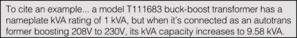
BarkFlash wrote: stevenal wrote: I'm not following your math here... 100KVA three phase 240V load. 100KVA / 240V / 1.732 *1000 = 240.56A, single phase would be even higher, 417A. stevenal wrote: VA is conserved so VA in is equal to VA out plus loss. True, VA is conserved, but it will not match the VA listed on the nameplate. See the attached picture in first comment or follow the link. It is not unusual for a BB Xfmr to supply a load 10x the nameplate rating, depending on the turns ratio. http://www.delzer.com/hubbell/acme_cat/#122/zstevenal wrote: I'm not sure how an auto is any more likely to saturate than any other. Agreed. But the fault at the secondary is not completely limited by xfmr impedance like it is in an iso-xfmr, because the secondary is wired directly to the primary. So modeling with an iso-xfmr would be incorrect. SKM Power Tools has a TYPE option in the Component Editor where you can select "Auto-TX Shell" or "Auto-TX Core" but it doesn't seem to do anything. I don't see another way of adding an Auto-Xfmr. Can ETAP or Easy Power do this? I think you're right that changing the connection type in SKM to Auto-TX Core doesn't do anything. Here's what SKM Help says on it: Attachment:
 autotransformers.jpg [ 256.12 KiB | Viewed 5538 times ]
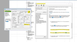
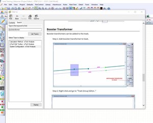
I don't know about EasyPower but I did a Help search in ETAP after I could not find that option to add an autotransformer or buck-boost in ETAP and it came back with this, among other things: Attachment:
 etap boost.jpg [ 149.58 KiB | Viewed 5538 times ]
That said, my experience level with ETAP isn't nearly what it is with SKM and I have not used whatever modeling method or operation ETAP is referring t there. If you have ETAP maybe you can do a similar search and get your answers.
_________________
SKM jockey for hire
PE in 17 states
|
|
| Top |
|
|
|
bbaumer
|
Post subject: Re: Modeling Buck-Boost Transformers? Posted: Thu Jul 13, 2023 10:27 am |
|
| Arc Level |
|
Joined: Fri Jul 08, 2016 10:01 am
Posts: 488
Location: Indiana
|
|
I will also add that I do not have the single phase module in SKM so I could not check to see if auto-transformer or buck-boost is an option in SKM if you have the single phase module. As far as I know there isn't such a thing as a 3 phase buck-boost transformer. You have to use 2 or 3 of them wired for 3 phase but I could be wrong there. Maybe you could use three single phase autotransformers wired together in the model if you have the single phase module. Not sure.
I did notice that in ETAP when I was looking at transformer attributes it does give you the option to model a three-phase transformer as 3 individual single phase cans wired for 3 phase like you'd commonly see on pole tops and sometimes in vaults.
_________________
SKM jockey for hire
PE in 17 states
|
|
| Top |
|
|
|
JBD
|
Post subject: Re: Modeling Buck-Boost Transformers? Posted: Sun Jul 16, 2023 6:30 pm |
|
Joined: Mon Jan 18, 2010 11:35 am
Posts: 609
Location: Wisconsin
|
bbaumer wrote: I will also add that I do not have the single phase module in SKM so I could not check to see if auto-transformer or buck-boost is an option in SKM if you have the single phase module. As far as I know there isn't such a thing as a 3 phase buck-boost transformer. You have to use 2 or 3 of them wired for 3 phase but I could be wrong there. Maybe you could use three single phase autotransformers wired together in the model if you have the single phase module. Not sure.
I did notice that in ETAP when I was looking at transformer attributes it does give you the option to model a three-phase transformer as 3 individual single phase cans wired for 3 phase like you'd commonly see on pole tops and sometimes in vaults. 3 single phase transformers connected into a three phase bank is considered and treated the same as a single three phase transformer. Pretty much the real difference between a buck-boost and a standard transformer is its very low impedance and the different L-G fault currents on 2 wire single-phase transformers where one leg is straight through and the other includes the transformer. I can't remember ever modeling a buck-boost transformer, so I have no idea how hard it is to determine its impedance.
|
|
| Top |
|
|
|
BarkFlash
|
Post subject: Re: Modeling Buck-Boost Transformers? Posted: Wed Jul 19, 2023 12:12 pm |
|
Joined: Wed Nov 23, 2022 8:53 am
Posts: 28
Location: Indiana
|
bbaumer wrote: I will also add that I do not have the single phase module in SKM so I could not check to see if auto-transformer or buck-boost is an option in SKM if you have the single phase module. As far as I know there isn't such a thing as a 3 phase buck-boost transformer. You have to use 2 or 3 of them wired for 3 phase but I could be wrong there. Maybe you could use three single phase autotransformers wired together in the model if you have the single phase module. Not sure.
I did notice that in ETAP when I was looking at transformer attributes it does give you the option to model a three-phase transformer as 3 individual single phase cans wired for 3 phase like you'd commonly see on pole tops and sometimes in vaults. Thanks for looking into it and the info. I happened to stumble across this in the IEEE Std-141 Red Book, Chapter 10 section 10.4 for completely different reasons. Attachment:
 Auto-TX Faults.png [ 49.1 KiB | Viewed 5526 times ]
_________________
Steward of the magic smoke genie.
|
|
| Top |
|
|
|
bbaumer
|
Post subject: Re: Modeling Buck-Boost Transformers? Posted: Wed Jul 19, 2023 3:06 pm |
|
| Arc Level |
|
Joined: Fri Jul 08, 2016 10:01 am
Posts: 488
Location: Indiana
|
BarkFlash wrote: bbaumer wrote: I will also add that I do not have the single phase module in SKM so I could not check to see if auto-transformer or buck-boost is an option in SKM if you have the single phase module. As far as I know there isn't such a thing as a 3 phase buck-boost transformer. You have to use 2 or 3 of them wired for 3 phase but I could be wrong there. Maybe you could use three single phase autotransformers wired together in the model if you have the single phase module. Not sure.
I did notice that in ETAP when I was looking at transformer attributes it does give you the option to model a three-phase transformer as 3 individual single phase cans wired for 3 phase like you'd commonly see on pole tops and sometimes in vaults. Thanks for looking into it and the info. I happened to stumble across this in the IEEE Std-141 Red Book, Chapter 10 section 10.4 for completely different reasons. Attachment: Auto-TX Faults.png Thanks for sharing that info.
_________________
SKM jockey for hire
PE in 17 states
|
|
| Top |
|
|
|
haze10
|
Post subject: Re: Modeling Buck-Boost Transformers? Posted: Mon Jul 24, 2023 7:00 am |
|
Joined: Thu Jan 10, 2008 8:49 pm
Posts: 520
Location: New England
|
|
With auto transformers only the secondary winding is in series with the line. The nameplate impedance is for both windings. I've never been able to find out how to determine the impedance of just the secondary in series. After much investigation, including contacting manufacturers, no one has been able to provide an accurate answer. Would love to find a white paper on the subject.
|
|
| Top |
|
|
|
stevenal
|
Post subject: Re: Modeling Buck-Boost Transformers? Posted: Mon Jul 24, 2023 2:07 pm |
|
Joined: Tue Jan 13, 2009 5:00 pm
Posts: 630
|
|
I'm not sure why you would want the secondary alone, since it is magnetically linked to the primary.
If the buck boost transformer nameplate kVA is based on the bucked or boosted capacity, the nameplate impedance % should follow. Suggest: Convert impedance % to ohms secondary, then convert to impedance % based on the through capacity. Now you have an equivalent 2 winding transformer you can model.
Per my understanding of IEEE standards, impedance of autotransformers is based on output volts and amps.
|
|
| Top |
|
|
 
|
Page 1 of 1
|
[ 11 posts ] |
|
|
You cannot post new topics in this forum
You cannot reply to topics in this forum
You cannot edit your posts in this forum
You cannot delete your posts in this forum
You cannot post attachments in this forum
|
|


