Current Status

Not Enrolled

Price

245.00

Get Started

Coordination Studies
On Demand Class | 6 Hours | 28 Modules | By Jim Phillips, P.E.

About the Class

An electrical coordination study, sometimes known as protective device coordination analysis, protection study and similar terms, is an “attempt” to select and set devices to minimize the extent of an outage when a fault or overload occurs.  Ideally only the device closest to the fault should operate and clear with the other devices remaining closed.  This minimizes the extent of the outage.

Accomplishing selectivity between devices typically requires that each device further upstream and closer to the source be a bit less sensitive and often have some intentional time delay.  This approach is good for selectivity but what about protection?  Setting devices with more time delay can result in unnecessary damage if the fault is to be cleared by a device that has delay.

Selectivity and protection are two competing objectives.  In this class, Jim Phillips takes you step by step though the coordination study training.  In addition, in this unique class based on his four decades of experience, he shows you how to manually construct the graphs which has become a lost art in the age of “there’s an app for that”

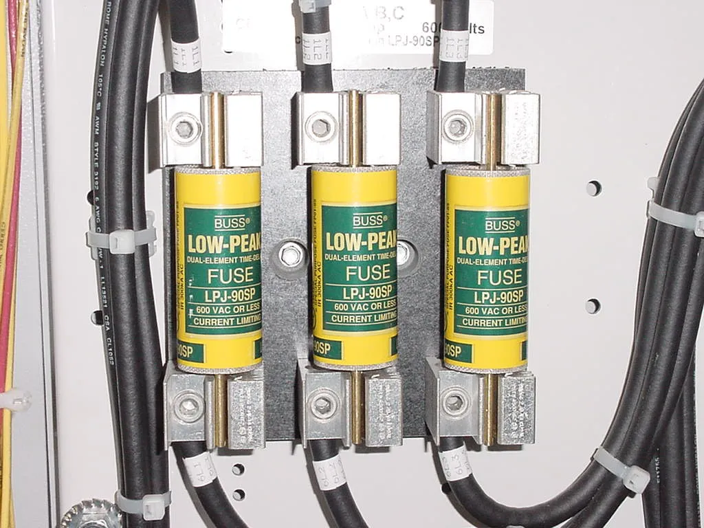
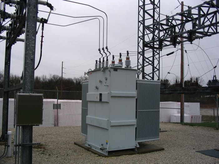
You will see how to make decisions regarding compromises in selectivity that are often necessary to achieve the best overall coordination.  You will also learn about ground fault protection, coordinating current limit fuses, electronic trip circuit breakers, setting protective relays as well as how to protect transformers based on the ANSI C57 thru fault curves.  The final case problem illustrates how to address making compromises when perfect coordination is not attainable.

This class was recorded during the week long “Electrical Power System Engineering Class”

Agenda​

COORDINATION STUDY REQUIREMENTS

Selective Coordination Basics, Understanding Time Current Curves (TCC), Data Requirements, Device Settings, Graph Scale Selection, Protection vs. Selectivity and Reliability, Compromises in Coordinating Devices in Series

SOLID STATE / ELECTRONIC TRIP BREAKERS

Long Time, Short Time, Instantaneous Settings, I2T Settings, Coordination of Electronic Trip Circuit Breakers, Eliminating Instantaneous for Coordination, NEC® Requirements for High Speed Fault Clearing for Reducing the Hazard From an Arc Flash

TRANSFORMER PROTECTION

NEC® Article 450 Requirements, Magnetizing Inrush Current, Using ANSI C57 Thru Fault Curves for Transformer Protection, Adjustments to the Thru Fault Curves Based on Transformer Winding Configurations, Setting Overcurrent Relays for Protecting a Transformer Based on ANSI C57

COORDINATION OF MOLDED CASE CIRCUIT BREAKERS

Molded Case Circuit Breaker Time Current Curves, Overload Region of TCC, Instantaneous Region, Fixed vs. Adjustable Instantaneous, Determining the Setting of the Instantaneous, Drawing Time Current Curves.  In Class Problem – Drawing Molded Case Circuit Breaker Time Current Curves, Selecting Settings for Optimal Selective Coordination, Evaluating What Happens During Mis-Coordination

OVERCURRENT RELAYS

Protective Relay Operation, Amp Tap Setting, Time Dial Operation and Setting, Instantaneous Function, Current Transformers, Necessary Protective Relay Time Margins for Selective Coordination, Setting Selection, Protective Relay Time Current Curves, Curve Shape – Inverse, Very Inverse, Extremely Inverse.  In Class Problems – Setting Overcurrent Relays and Relay Coordination Studies

COORDINATION OF FUSES

Time Current Curves of Fuses, Current Limiting vs. Non Current Limiting Fuse Curves, Minimum Melting and Total Clearing Curves, Coordinating Two Sets of Current Limiting Fuses with Selectivity Tables, Coordinating I2T Let-Thru Energy.  In Class Problems – Coordinating Fuses with Each Other and Fuse and Circuit Breaker Coordination

CASE PROBLEM

Coordination Study of Small Industrial Plant, Determining Optimal Device Settings and Drawing Time Current Curves for Multiple Devices in Series.

GROUND FAULT RELAYS

Residually Connected Ground Fault Schemes, Zero Sequence Ground Fault Relaying, Settings, NEC® Requirements for Ground Fault Protection of Services, Feeders and Equipment, Nuisance Tripping, Setting Ground Fault Devices

TIME CURRENT CURVES AT TWO DIFFERENT VOLTAGE LEVELS

Evaluate what happens when coordinating a transformer primary and secondary device at two different voltage levels.  See how to adjust the TCCs

Course Content

Download: Time Current Curves
Module 1: Introduction to Coordination Studies | Duration 12:05
Module 2: Coordination Basics and Time Current Curves | Duration 17:29
Module 8: Details and Evaluation of Miscoordination | Duration 11:15
Module 9: Electronic Trip Circuit Breakers | Duration 08:28
Module 10: Coordinating Electronic Trip CB and Fuses | Duration 08:53
Module 11: Using Different Segments and I^2T Function | Duration 05:19
Module 12: L,S,I functions and Perfect Coordination | Duration 04:20
Module 13: Ground Fault Protection | Duration 12:25
Module 14: Zone Selective Interlocking | Duration 05:42
Module 15: Determining Coordination Priority | Duration 10:41
Module 17: Transformer Protection Basics | Duration 11:06
Module 20: ANSI C57 Thru-Fault Curves | Duration 12:37
Module 22: Introduction to Overcurrent Relays | Duration 10:10
Module 25: Time Current Curves at Different Voltages | Duration 06:04
Module 27: Motor Protection Time Current Curves | Duration 04:23
Final Quiz: Coordination Studies