Question: Why isn’t there a fixed percentage difference between the bolted and arcing fault current?
IEEE 1584, Guide for Performing Arc-Flash Hazard Calculations, provides the technical foundation used to calculate incident energy and arc-flash boundaries in electrical power systems. A key element in this standard is the calculation of the arcing fault current, which differs from the bolted fault current typically obtained from short-circuit studies. While IEEE 1584 defines the calculation methodology, NFPA 70E relies on these results as part of an arc flash risk assessment used to establish practical electrical safety requirements for workers.
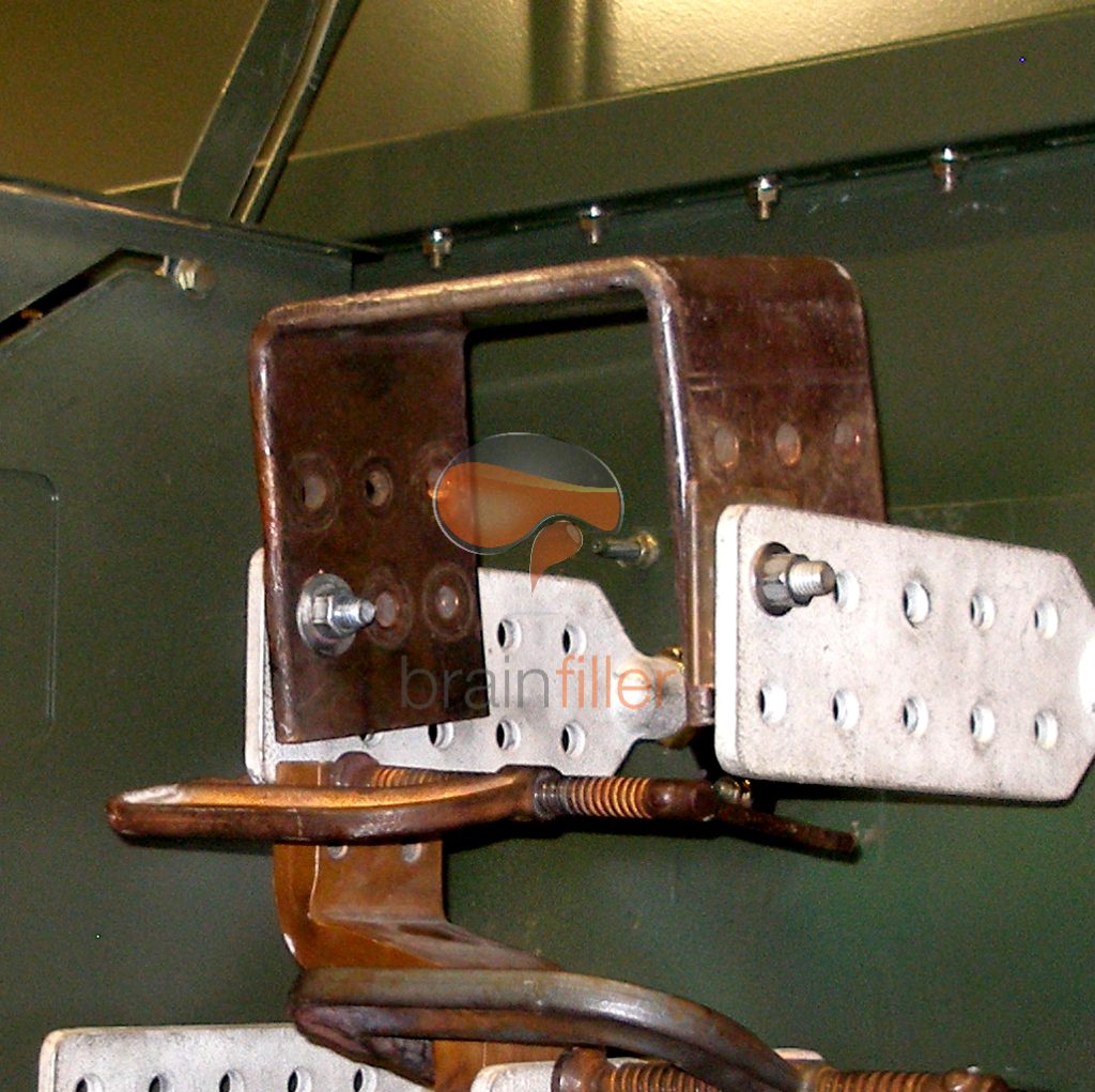
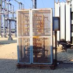
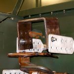
A bolted fault represents a theoretical condition with zero impedance between conductors, resulting in the maximum available fault current. The term reflects laboratory conditions during a short circuit test. When calibrating the circuit, the test circuit is shorted by “bolting” the phases together with large bus bars as I have done in the laboratory and illustrated in the photo. Hence the term “bolted fault current”
An arcing fault, however, includes the impedance of the electrical arc itself, which limits current flow. For this reason, arcing fault current is always lower than bolted fault current.
The first theoretically derived equations from the 1980’s did not account for the arcing current and only used the bolted fault current. Subsequent work in the late 1990’s recognized the importance of the arcing current and its potential effect on how a protective device may operate. This later work referenced technical research that indicated the arcing current at 480v could be as low as 38 percent of the bolted current and therefore 38 percent was a “fixed” value that was suggested.
Research that was part of the development of the 2002 Edition of IEEE 1584 determined the percentage difference between bolted and arcing fault current varies significantly with system voltage and also the magnitude of bolted fault current, which directly affects arc-flash hazard analysis results used to comply with NFPA 70E 130.5 Arc Flash Risk Assessment.
At lower system voltages, particularly in the 208 V to 600 V range, the arc impedance is relatively high compared to the system impedance. This results in a larger percentage reduction between bolted and arcing fault current. In many low-voltage systems, the arcing current may be substantially lower than bolted fault current. This can cause protective devices to operate in their time-delay region resulting in a significant increase in the arc duration and incident energy.
The bolted fault current follows a similar trend. Higher bolted fault currents correspond to a lower system impedance. As with the voltage trend, this means that the arc impedance represents a larger portion of the total circuit impedance in systems with higher available fault current. Conversely, as the bolted fault current decreases, the percentage difference between the bolted fault current and the arcing fault current also decreases.
In each case, the percentage difference between the bolted and arcing current is not a linear relationship and must be calculated using very robust equations from IEEE 1584.
Arc flash studies used to comply with NFPA 70E requirements, recognize this relationship and an arc-flash risk assessment based on incident energy calculations needs to account for realistic arcing conditions rather than relying solely on maximum short-circuit current.
As system voltage increases such as medium voltage systems, the electrical arc becomes more stable and the arc impedance relative to the system impedance has less impact. Consequently, the difference between bolted and arcing fault current decreases, and arcing current more closely approaches bolted fault current. This behavior is reflected in IEEE 1584 calculation models and directly influences incident energy values used to determine PPE arc ratings, arc-flash boundaries, and safe work practices under NFPA 70E.
For systems above 15 kV, the difference between bolted and arcing fault current is minimal. Alternative arc flash models above 15 kV treat these values as effectively the same for higher voltages.
In practice, NFPA 70E establishes the “what” of electrical safety—risk assessment, labeling, PPE, and work practices—while IEEE 1584 defines the “how” of arc-flash calculations. Understanding how arcing fault current varies with voltage and other factors is one of the many critical steps in performing arc flash studies that support compliance with NFPA 70E and improve worker safety.
With a career beginning in 1981 and Brainfiller launching in 1987, Jim has built a global reputation as a trusted leader in electrical safety.
He currently:
💡 Did you know? Many NFPA 70E trainers learn the material by attending Jim’s classes—while Jim is involved directly with the standards they teach.


Jim’s background spans:
This progression gives Jim a rare, 360-degree view of electrical hazards—from theoretical models to real-world failures. His training incorporates both the engineering and the practical side of electrical safety.
In the early 2010s, NFPA 70E began shifting from a hazard-based approach to a risk-based methodology. Jim contributed to this evolution through published research and committee discussions. His early collaboration with a UK colleague helped introduce the risk-focused thinking now central to each new edition.
He continues to evaluate public input, technical proposals, and revisions each cycle—bringing real-world insight to the standard.
Brainfiller offers several courses designed and taught by Jim, all targeted to engineers, electricians, and safety professionals.
NFPA 70E Qualified Worker Training (8 hours)
Covers risk assessment, PPE, LOTO, establishing an electrically safe work condition, and auditing requirements.
How to Perform an Arc-Flash Study | IEEE 1584 (16 hours)
Modeling, arcing current, incident energy, arc-flash boundaries, and system-level mitigation.
Fundamentals of Electrical Safety (2 hours)
Shock hazards, arc-flash basics, and the building blocks behind NFPA 70E.
DC Electrical Safety Fundamentals (2 hours)
Key safety practices for data centers and DC systems.
All training is available live, on-site, or on-demand, and includes completion certificates with CEU/PDH documentation.
Because Jim is embedded in NFPA, IEEE, IEC, and NEC committees, he sees emerging trends before they appear in the codebook.
His training materials are updated immediately after each standards cycle, keeping teams aligned with NFPA 70E, IEEE 1584, and OSHA expectations.
🔧 From code to craft: Jim explains why requirements exist and how to apply them correctly in real electrical systems.


| Cookie | Duration | Description |
|---|---|---|
| cookielawinfo-checbox-analytics | 11 months | This cookie is set by GDPR Cookie Consent plugin. The cookie is used to store the user consent for the cookies in the category "Analytics". |
| cookielawinfo-checbox-functional | 11 months | The cookie is set by GDPR cookie consent to record the user consent for the cookies in the category "Functional". |
| cookielawinfo-checbox-others | 11 months | This cookie is set by GDPR Cookie Consent plugin. The cookie is used to store the user consent for the cookies in the category "Other. |
| cookielawinfo-checkbox-necessary | 11 months | This cookie is set by GDPR Cookie Consent plugin. The cookies is used to store the user consent for the cookies in the category "Necessary". |
| cookielawinfo-checkbox-performance | 11 months | This cookie is set by GDPR Cookie Consent plugin. The cookie is used to store the user consent for the cookies in the category "Performance". |
| viewed_cookie_policy | 11 months | The cookie is set by the GDPR Cookie Consent plugin and is used to store whether or not user has consented to the use of cookies. It does not store any personal data. |