A short circuit happens when energized conductors accidentally make contact with each other and/or to ground. When that connection forms, the load and its impedance is bypassed resulting usually resulting in a very high magnitude of current. There are several fault types—three-phase, phase-to-phase, and line-to-ground, but the line-to-ground fault is by far the most common. You’ll often see numbers in the 70–80% of all faults falling into this category. Some say this number is even higher.
Why so many line-to-ground faults? It’s simple probability. Think about your car. Have you ever had all four tires go flat at the exact same time? It’s possible, but it would take something unusual—like driving through serious debris. Much more likely is losing one tire to wear or a nail as shown in Figure 1. (and yes, that has happened to me – more than once!)
Electrical systems behave the same way. Even though we have three energized phases, the odds of all three faulting simultaneously are relatively low. Three-phase faults usually require some outside influence—like someone forgetting to remove temporary grounding jumpers, or heavy equipment such as a crane or backhoe making unintended contact. Most of the time, it’s just one phase finding ground.


Let’s face it. Things can go wrong due to a wide variety of reasons. Ground faults don’t always start as high magnitude currents. They can begin as low-level, intermittent arcing currents. In those cases, the standard phase overcurrent devices may not see enough current to trip quickly—or at all. The result can be prolonged arcing and significant equipment damage.
At the other end of the spectrum, you can have a solid (bolted) ground fault with very high current. In that case, the phase overcurrent protection will almost certainly operate quickly. So ground faults can range from subtle and sneaky to violent and immediate.
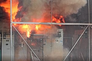
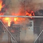
When current jumps an air gap between conductors, you get an arc flash. That arc produces intense heat, pressure waves, ultraviolet radiation, molten metal, and shrapnel. It’s not just an electrical problem—it’s a serious safety hazard that I discuss in several of my training programs.
If an arc flash starts as a single line-to-ground event, it doesn’t necessarily stay that way. The conducting plasma created by the arc can easily bridge to the second and third phases. When that happens, the event escalates into a three-phase arc flash.
And here’s the key point: that escalation can happen in just a few cycles—almost instantaneously. Can we predict when a single-phase arc will transition into three-phase? No. There’s no reliable way to know. That’s why arc flash incident energy calculations assume a three-phase condition. It’s the conservative / worst case approach.
So what if we could stop a single-phase arc flash from developing significant energy in the first place? If the ground fault current is limited enough, there may not be sufficient energy to sustain or escalate the arc.
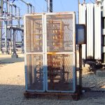
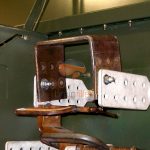
This is exactly what impedance grounding does—typically by installing a neutral grounding resistor (NGR). An NGR is connected between the system neutral (such as the wye point of a transformer or generator) and the grounding electrode system as shown in Figure 2. Its job is to intentionally limit ground fault current to a controlled value.
The NEC lays out conditions for using a neutral grounding resistor. Sections 250.36 and 270.36 specify that:
These requirements ensure the system is properly monitored and maintained.
High-resistance grounding is commonly used where uptime is critical. In an HRG system, the NGR is sized to limit ground fault current to a very low level—typically between 1 and 10 amps.
At this current level, a single line-to-ground fault does not require an immediate shutdown. The system can continue operating while alarms and indicator lights alert personnel that a fault exists. Maintenance teams can then track down the issue and correct it, or schedule an orderly shutdown if needed.
That’s a big deal for industrial processes. However, leaving a ground fault on the system indefinitely isn’t a good idea. If a second ground fault occurs on another phase, you now have a phase-to-phase fault—and that will result in a forced, and likely disruptive, shutdown.
Low-resistance grounding is more common on medium-voltage systems. At higher voltages, you often have significant capacitive charging current, especially when shielded cables are involved. The larger the distribution system and the more cable installed, the greater the total capacitance—and therefore the higher the charging current.
In these situations, high-resistance grounding may not work well because the charging current that exists. Instead, a low-resistance grounding system is used.
With LRG, the resistor is sized to allow a higher ground fault current—typically in the 100 to 1000 amp range. This level is intentionally set above the system’s capacitive charging current so that protective devices such as relays can reliably detect and isolate the fault quickly.
Beyond equipment protection and system reliability, impedance grounding provides a major safety advantage and is one of the methods listed for “safety by design” By significantly limiting ground fault current—especially in high-resistance grounded systems—the energy available during a single-phase arc flash can be drastically reduced and almost eliminated in many cases.
If the ground fault current is low enough, the arc will likely not escalate into a three-phase event. In short, neutral grounding resistors aren’t just about system performance—they can play a critical role in reducing arc flash hazards and improving overall electrical safety.


As Vice-Chair of IEEE 1584, Jim has played a major role in shaping the methodology behind modern arc-flash hazard calculations—the backbone of NFPA 70E’s incident energy analysis and PPE selection.
His instruction includes:

All training is available live, on-site, or on-demand, and includes completion certificates with CEU/PDH documentation.NFPA 70E Qualified Worker Training (8 hours)
Covers risk assessment, PPE, LOTO, establishing an electrically safe work condition, and auditing requirements.How to Perform an Arc-Flash Study | IEEE 1584 (16 hours)
Modeling, arcing current, incident energy, arc-flash boundaries, and system-level mitigation.Fundamentals of Electrical Safety (2 hours)
Shock hazards, arc-flash basics, and the building blocks behind NFPA 70E.DC Electrical Safety Fundamentals (2 hours)
Key safety practices for data centers and DC systems.


| Cookie | Duration | Description |
|---|---|---|
| cookielawinfo-checbox-analytics | 11 months | This cookie is set by GDPR Cookie Consent plugin. The cookie is used to store the user consent for the cookies in the category "Analytics". |
| cookielawinfo-checbox-functional | 11 months | The cookie is set by GDPR cookie consent to record the user consent for the cookies in the category "Functional". |
| cookielawinfo-checbox-others | 11 months | This cookie is set by GDPR Cookie Consent plugin. The cookie is used to store the user consent for the cookies in the category "Other. |
| cookielawinfo-checkbox-necessary | 11 months | This cookie is set by GDPR Cookie Consent plugin. The cookies is used to store the user consent for the cookies in the category "Necessary". |
| cookielawinfo-checkbox-performance | 11 months | This cookie is set by GDPR Cookie Consent plugin. The cookie is used to store the user consent for the cookies in the category "Performance". |
| viewed_cookie_policy | 11 months | The cookie is set by the GDPR Cookie Consent plugin and is used to store whether or not user has consented to the use of cookies. It does not store any personal data. |